+91-9619103479
or
vishal@solitaire-overseas.com
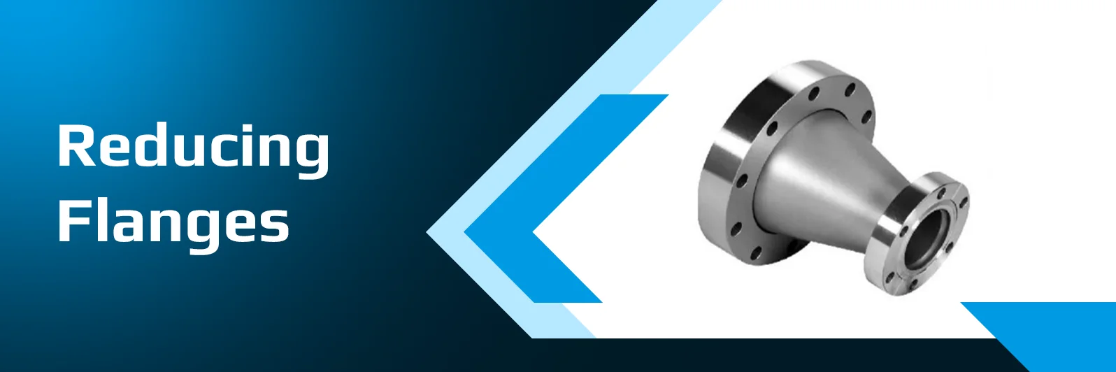
Carbon Steel Reducing Flanges are a convenient solution when joining pipes of various nominal sizes together without having to use a separate reducer between flanged joints. These are made of forged carbon steel and their flange connection with reduced bore enables size changes in piping systems. They are typically manufactured in ASTM A105 for normal-temperature use and ASTM A350 LF2 for special low-temperature uses. They may be offered in Weld Neck, Slip-On, Blind, Threaded, Socket Weld and Lap Joint sizes and pressure classes as per relevant ASME standards. These flanges are popular in oil and gas, petrochemical, chemical, power, and process industries. Solitaire Overseas is a trusted and leading Carbon Steel Reducing Flanges Manufacturer and Supplier in India and supplies quality tested products with complete material documents.
| Feature / Parameter | Standard Specification Values |
|---|---|
Material Specifications |
ASTM A105 / ASME SA105 (Ambient & Higher Temp); ASTM A350 LF2 Class 1 / Class 2 (Low-Temperature -46°C) |
Dimensional Standards |
ASME B16.5 (½″ to 24″), ASME B16.47 Series A & B (26″ to 60″), MSS SP-44 |
Size Range |
Large Nominal Size: 1″ to 48″ |
Pressure Ratings |
Class 150#, 300#, 400#, 600#, 900#, 1500#, 2500# (PN10 to PN400) |
Flange Facing Types |
Raised Face (RF), Flat Face (FF), Ring Type Joint (RTJ), Male & Female (M&F), Tongue & Groove (T&G) |
Manufacturing Methods |
Precision Die Forged, Drop Forged, Machined |
Heat Treatment |
As-Forged, Normalized (A105N / LF2), Annealed, Quenched & Tempered |
Quality Testing |
Hardness, Tensile, PMI, Hydrostatic, Ultrasonic, Charpy V-Notch (for A350 LF2 at -46°C) |
Certification |
Mill Test Certificate per EN 10204 3.1 / 3.2, NACE MR0175 / MR0103 compliance |
| Material Grade | Carbon (C) | Manganese (Mn) | Phosphorus (P) | Sulfur (S) | Silicon (Si) | Copper (Cu) | Nickel (Ni) | Chromium (Cr) | Molybdenum (Mo) | Vanadium (V) | Niobium (Nb) |
|---|---|---|---|---|---|---|---|---|---|---|---|
ASTM A105 |
0.35 max |
0.60–1.05 ¹ |
0.035 max |
0.040 max |
0.10–0.35 |
0.40 max ² |
0.40 max ² |
0.30 max ², ³ |
0.12 max ², ³ |
0.08 max ² |
— |
ASTM A350 LF2 Class 1 |
0.30 max |
0.60–1.35 |
0.035 max |
0.040 max |
0.15–0.30 |
0.40 max |
0.40 max |
0.30 max |
0.12 max |
0.08 max |
0.02 max |
ASTM A350 LF2 Class 2 |
0.30 max |
0.60–1.35 |
0.035 max |
0.040 max |
0.15–0.30 |
0.40 max |
0.40 max |
0.30 max |
0.12 max |
0.08 max |
0.02 max |
| Material Grade | Tensile Strength, min | Yield Strength, min (0.2% offset) | Elongation in 2 in. (50mm), min | Reduction of Area, min | Hardness, max | Charpy Impact Test Temp | Impact Energy, min (Avg / Single) |
|---|---|---|---|---|---|---|---|
ASTM A105 |
70 ksi [485 MPa] |
36 ksi [250 MPa] |
22% |
30% |
187 HBW |
Not Required |
— |
ASTM A350 LF2 Class 1 |
70–95 ksi [485–655 MPa] |
36 ksi [250 MPa] |
22% |
30% |
197 HBW |
-46°C [-50°F] |
15 ft-lbf / 12 ft-lbf [20 J / 16 J] |
ASTM A350 LF2 Class 2 |
70–95 ksi [485–655 MPa] |
36 ksi [250 MPa] |
22% |
30% |
197 HBW |
-18°C [0°F] |
15 ft-lbf / 12 ft-lbf [20 J / 16 J] |
| ASTM Standard | US (ASME) | EN / DIN (Europe/Germany) | BS (UK) | JIS (Japan) | AFNOR (France) | IS (India) |
|---|---|---|---|---|---|---|
ASTM A105 |
ASME SA105 |
C22.8 / P250GH (1.0460) |
BS 1503 224 Gr. 490 |
JIS G3201 SF440A |
AFNOR A42 BF |
IS 2062 Gr. B / IS 1875 Class 2 |
ASTM A350 LF2 |
ASME SA350 LF2 |
TStE 355 / P355QH (1.0566) |
BS 1503 224 Gr. 490 LT46 |
JIS G3205 SFL2 |
AFNOR A350 LF2 |
IS 2062 E350 (Impact Tested) |
| Nominal Size (Large × Small) | Outer Diameter (OD) (mm) | Bolt Circle Dia (PCD) (mm) | Number of Bolts | Bolt Hole Diameter (mm) | Flange Thickness (T) (mm) | Hub Diameter (H) (mm) | Approx Weight (kg) |
|---|---|---|---|---|---|---|---|
2″ × 1″ |
152 |
120.7 |
4 |
19.1 |
19.1 |
77.7 |
2.5 |
2″ × 1½″ |
152 |
120.7 |
4 |
19.1 |
19.1 |
77.7 |
2.3 |
3″ × 1½″ |
191 |
152.4 |
4 |
19.1 |
23.9 |
108.0 |
4.8 |
3″ × 2″ |
191 |
152.4 |
4 |
19.1 |
23.9 |
108.0 |
4.5 |
4″ × 2″ |
229 |
190.5 |
8 |
19.1 |
23.9 |
134.9 |
7.2 |
4″ × 3″ |
229 |
190.5 |
8 |
19.1 |
23.9 |
134.9 |
6.8 |
6″ × 3″ |
279 |
241.3 |
8 |
22.2 |
25.4 |
192.0 |
11.5 |
6″ × 4″ |
279 |
241.3 |
8 |
22.2 |
25.4 |
192.0 |
10.8 |
8″ × 4″ |
343 |
298.5 |
8 |
22.2 |
28.6 |
246.1 |
18.2 |
8″ × 6″ |
343 |
298.5 |
8 |
22.2 |
28.6 |
246.1 |
16.5 |
10″ × 6″ |
406 |
362.0 |
12 |
25.4 |
30.2 |
304.8 |
26.0 |
10″ × 8″ |
406 |
362.0 |
12 |
25.4 |
30.2 |
304.8 |
23.8 |
12″ × 8″ |
483 |
431.8 |
12 |
25.4 |
31.8 |
365.0 |
38.5 |
12″ × 10″ |
483 |
431.8 |
12 |
25.4 |
31.8 |
365.0 |
34.0 |
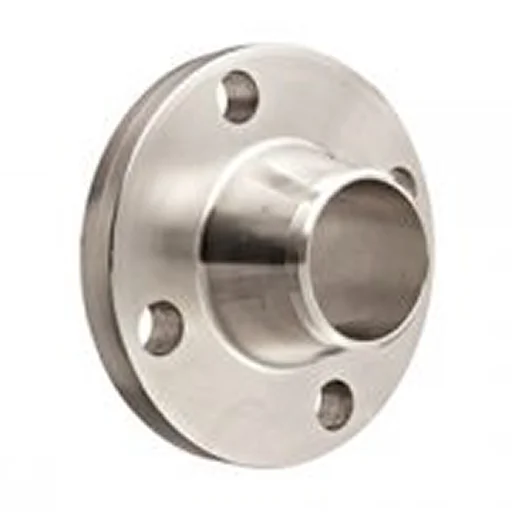
Weld Neck Flange
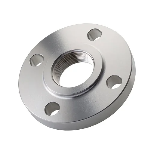
Threaded Flange
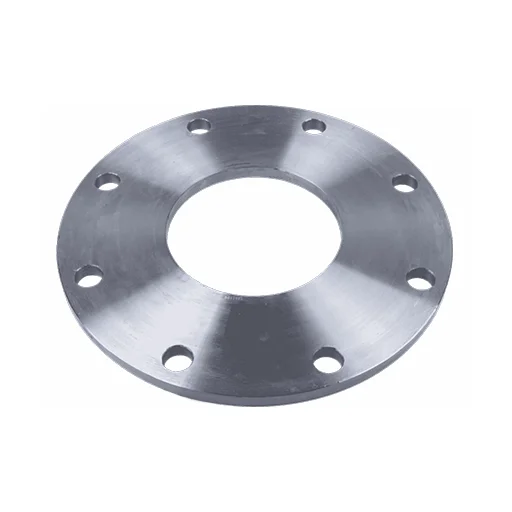
Slip-on Flange
Carbon Steel Reducing Flanges are piping components that connect pipes of different nominal sizes while combining the flange and size-reduction function in one component.
They are used to connect different pipe sizes directly at a flanged joint, eliminating the need for a separate pipe reducer in suitable piping arrangements.
A standard flange has a bore matching the connected pipe size, while a reducing flange has a smaller or larger bore to accommodate a different pipe size.
Yes, Carbon Steel Reducing Flanges can be welded when the selected material and flange configuration are suitable and qualified welding procedures are followed.
Yes, ASTM A105 carbon steel reducing flanges can be used for elevated-temperature service when the applicable pressure-temperature ratings are satisfied.
Yes, ASTM A350 LF2 reducing flanges are suitable for specified low-temperature applications when the required impact toughness and design conditions are met.