+91-9619103479
or
vishal@solitaire-overseas.com
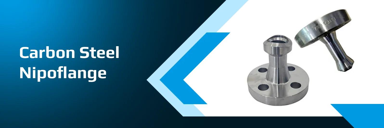
Carbon Steel Nipoflange is a forged branch connection with flange to offer a bolted outlet directly from main pipeline. It is contoured in the neck to weld to the run pipe, with the flanged end connected to valves, instruments, and auxiliary piping, eliminating the need for a separate branch fitting, nipple, and flange assembly. Nipoflanges are typically used in oil and gas pipelines, refineries, petrochemical plants and other industrial process systems to make branch connections easier and fewer fabricated joints. Selection depends on the header size and schedule, branch size, pressure class, material grade and flange facing. Solitaire Overseas is a business based in India, which is a trusted manufacturer and supplier of carbon steel nipo flanges for the industrial projects across the globe.
| Parameter | Technical Specification |
|---|---|
|
Product Description |
Carbon steel nipoflange: One-piece forged branch component integrating a reinforced contoured branch connection, an extended nipple neck, and an ASME B16.5 flanged outlet end. |
|
Primary Material Grades |
Ambient / Elevated Temp: ASTM A105 / SA-105 (Normalized A105N execution) Low-Temperature Service: ASTM A350 LF2 Class 1 / SA-350 (Impact tested at -46°C) |
|
Flange-End Standards |
ASME B16.5 for NPS 1/2" to 24"; larger sizes manufactured in accordance with ASME B16.47 Series A & B or customer engineering drawings. |
|
Branch-Outlet Design Standard |
Integrally reinforced contoured weld outlet conforming to MSS SP-97 requirements for branch connections. |
|
Pressure Class Ratings |
ASME Class 150, Class 300, Class 600, Class 900, Class 1500, and Class 2500 |
|
Branch (Flange) Sizes |
Standard range: NPS 1/2" to 2"; extended engineered range up to NPS 8" |
|
Run (Header) Sizes |
Contoured base matched to specific header run pipe sizes from NPS 1/2" through NPS 36" (and flat base execution for header sizes >36"). |
|
Neck Schedule & Length |
Standard schedules: Schedule 80 (XS), Schedule 160, and XXS. Available in standard 3.1/2" (89mm) and 5.1/2" (140mm) body lengths or extended lengths to project drawing. |
|
Facing Configurations |
Raised Face (RF) 125250 n AARH}, Flat Face (FF), and Ring-Type Joint (RTJ) grooved (R series). |
|
Manufacturing Execution |
100% Solid Die-Forged execution (one-piece construction without circumferential welds), heat-treated, and precision CNC machined. |
|
Testing & Inspection |
Chemical heat analysis, mechanical tensile/yield testing, Brinell hardness survey, Charpy V-Notch impact testing at -46°{C} for LF2, Ultrasonic Testing (UT), Magnetic Particle Inspection (MPI), and Positive Material Identification (100% PMI). |
|
Certification & Traceability |
Certified Material Test Report (CMTR) supplied to EN 10204 Type 3.1 as standard; EN 10204 Type 3.2 available with Third-Party Inspection (TPI) sign-off on request. |
|
Product Marking & Traceability |
Die-stamped on outer flange rim per ASME B16.5 / MSS SP-97: • Manufacturer Logo / Name • Material Grade (e.g., A105N or A350-LF2 CL1) • Flange Size & Class Rating • Neck Schedule / Thickness & Header Run Size • Unique Melt Heat Number for full CMTR traceability |
| Chemical Property | ASTM A105 | ASTM A350 LF2 Class 1 |
|---|---|---|
|
Carbon (C), max |
0.35% |
0.30% |
|
Manganese (Mn) |
0.60 – 1.05% |
0.60 – 1.35% |
|
Phosphorus (P), max |
0.035% |
0.035% |
|
Sulphur (S), max |
0.040% |
0.040% |
|
Silicon (Si) |
0.10 – 0.35% |
0.15 – 0.30% |
|
Copper (Cu), max |
0.40% |
0.40% |
|
Nickel (Ni), max |
0.40% |
0.40% |
|
Chromium (Cr), max |
0.30% |
0.30% |
|
Molybdenum (Mo), max |
0.12% |
0.12% |
| Mechanical Property | ASTM A105 | ASTM A350 LF2 Class 1 |
|---|---|---|
|
Tensile Strength |
485 MPa min (70 ksi) |
485 – 655 MPa (70 – 95 ksi) |
|
Yield Strength (0.2% offset), min |
250 MPa (36 ksi) |
250 MPa (36 ksi) |
|
Elongation in 2 in. (50 mm), min |
22% |
22% |
|
Brinell Hardness, max |
187 HBW |
197 HBW |
|
Charpy V-Notch Impact Test |
Not required by default standard |
−46°C (−50°F): 20 J average, 16 J minimum (full-size 1010mm specimen) |
| Branch NPS | Class 150 OD (mm) | Class 150 Bolt Circle (mm) | Class 150 Holes × Dia. (mm) | Class 300 OD (mm) | Class 300 Bolt Circle (mm) | Class 300 Holes × Dia. (mm) |
|---|---|---|---|---|---|---|
|
1" |
108.0 |
79.4 |
4 × 15.9 |
123.8 |
88.9 |
4 × 19.1 |
|
1½" |
127.0 |
98.4 |
4 × 15.9 |
155.6 |
114.3 |
4 × 22.2 |
|
2" |
152.4 |
120.7 |
4 × 19.1 |
165.1 |
127.0 |
8 × 19.1 |
|
3" |
190.5 |
152.4 |
4 × 19.1 |
209.6 |
168.3 |
8 × 22.2 |
|
4" |
228.6 |
190.5 |
8 × 19.1 |
254.0 |
200.2 |
8 × 22.2 |
|
6" |
279.4 |
241.3 |
8 × 22.2 |
317.5 |
269.9 |
12 × 22.2 |
|
8" |
342.9 |
298.5 |
8 × 22.2 |
381.0 |
330.2 |
12 × 25.4 |
| Class | Rating (psig, ambient to 38°C) | Rating (bar, approx.) |
|---|---|---|
|
150 |
285 |
19.6 |
|
300 |
740 |
51.0 |
|
600 |
1,480 |
102.1 |
|
900 |
2,220 |
153.2 |
|
1500 |
3,705 |
255.3 |
|
2500 |
6,170 |
425.5 |
A carbon steel nipoflange is a forged flange with an integral nipple-style neck. The contoured end is welded to a run pipe to form a flanged branch, and the flange face bolts to a mating flange. It is usually made from ASTM A105 or, for low temperature, A350 LF2.
Both are forged flanged branch outlets welded to a header. A nipoflange has a nipolet-style neck, while a weldoflange has a weldolet-style reinforced body. Suppliers use the names loosely, so confirm the design from the drawing and the header size given.
No. A long weld neck flange has an extended neck and is butt-welded to a pipe end; it has no contour for a header. A nipoflange is welded onto the side of a run pipe, so the order must state the header size and schedule.
The flange end follows ASME B16.5 for class, facing and bolting. The branch-outlet body is commonly designed to MSS SP-97 for integrally reinforced outlets or to a manufacturer standard or drawing. Confirm the basis with your supplier before ordering.
A105 suits general service from ambient to elevated temperatures. A350 LF2 Class 1 is impact tested for low temperature, down to about −46°C. Choose by the minimum design temperature in your specification, and match the neck and run pipe grades.
The flange class sets the flange rating – for example, Class 300 in A105 is 740 psig at ambient temperature, and less as temperature rises. The neck wall and the weld to the run pipe must also suit the design conditions, so the lowest rating governs.
Integrally reinforced outlets are designed to provide reinforcement, but the piping designer must still check the branch against ASME B31.3 or the project code, including header wall, branch size and design conditions. Your engineer decides whether a nipoflange is acceptable.
Give the header size and schedule, branch flange size, class and facing, neck schedule and length, material, any drawing or standard, certificates and quantity. A sketch avoids confusion with long weld neck flanges and other branch fittings.