+91-9619103479
or
vishal@solitaire-overseas.com
ASTM A105 Flanges are forged carbon steel flanges used to form robust connections between pipelines. It’s made from ASTM A105 carbon steel, they ensure mechanical strength and good performance at room temperatures and elevated temperatures, both in oil and gas, petrochemicals, power plants and industrial processing systems. There are several types of flanges that include Weld Neck, Slip-On, Blind, Socket Weld, Threaded and Lap Joint flanges whose size and pressure class are determined based on the requirements of the pipe system. The difference from the material is that the sizes of the flanges comply with ASME B16.5 and ASME B16.47 standards. Solitaire Overseas is an experienced manufacturer and supplier of ASTM A105 Flanges in India.
|
Feature / Parameter |
Specification Details |
|
Material Specification |
ASTM A105 & ASME SA105, A105N |
|
Dimensional Standards |
ANSI/ASME B16.5, B16.47 Series A & B, B16.48, BS 4504, BS 10, EN-1092, DIN, etc. |
|
Standard |
ANSI Flanges, ASME Flanges, BS Flanges, DIN Flanges, EN Flanges, etc. |
|
Size Range |
1/2″ to 48″ |
|
Class / Pressure Rating |
Class 150 LBS, Class 300 LBS, Class 600 LBS, Class 900 LBS, Class 1500 LBS, Class 2500 LBS |
|
Flange Face Type |
Flat Face (FF), Raised Face (RF), Ring Type Joint (RTJ) |
|
Design Standards (By Region) |
DIN, JIS, ANSI, BS, PN, EN, ASA, ASME |
|
Flange Machining Equipment |
Sand-blasting machine, Press machine, Bending machine, Pushing Machine, Electric bevelling machine, etc. |
|
Connection Type |
Large Male-Female (LMF), Small Male-Female (SMF), Raised Face (RF), Flat Face (FF), Ring Type Joint (RTJ), Lap Joint Face (LJF) |
|
Production Process |
Machined, Forged, Heat Treated |
|
Element |
Carbon (C) |
Manganese (Mn) |
Phosphorus (P) |
Sulfur (S) |
Silicon (Si) |
Copper (Cu) |
Nickel (Ni) |
Chromium (Cr) |
Molybdenum (Mo) |
Vanadium (V) |
|
Composition (%) |
0.35 max |
0.60–1.05 |
0.035 max |
0.040 max |
0.10–0.35 |
0.40 max (1) |
0.40 max (1) |
0.30 max (1-2) |
0.12 max (1-2) |
0.08 max |
|
Property / Material Grade |
Tensile Strength, min |
Yield Strength (0.2% Offset), min |
Elongation (in 2″ / 50mm), min |
Reduction of Area, min |
Hardness (Brinell), max |
Thermal Conductivity |
Mean Coeff. of Thermal Expansion |
Charpy V-Notch Impact Test Temp & Energy |
|
ASTM A105 |
70,000 psi [485 MPa] |
36,000 psi [250 MPa] |
22% |
30% |
187 HBW |
360 BTU·in/(hr·ft²·°F) |
6.7 × 10â»â¶ in/in/°F |
N/A (Standard Ambient) |
|
Property |
Density |
Specific Gravity |
Specific Heat |
Melting Point |
Thermal Conductivity |
Mean Coeff. Thermal Expansion |
Modulus of Elasticity (Tension) |
Modulus of Elasticity (Torsion) |
|
Value |
0.284 lb/cu. in. |
7.9 |
0.107 Btu/lb/°F [32–212 °F] |
2740 °F |
360 |
6.7 |
30 |
11 |
|
Standard System |
Standard / Class |
Flange Outer Diameter (mm) |
Bolt Circle Diameter (mm) |
Number of Bolts |
Bolt Size |
Diameter of Bolt Hole (mm) |
|
AS 4087 |
PN14 |
95 |
67 |
4 |
M12 |
14 |
|
AS 2129 |
Table C |
95 |
67 |
4 |
13 |
14 |
|
Table D |
95 |
67 |
4 |
13 |
14 |
|
|
Table E |
95 |
67 |
4 |
13 |
14 |
|
|
Table F |
95 |
67 |
4 |
13 |
14 |
|
|
Table H |
114 |
83 |
4 |
16 |
17 |
|
|
Table J |
114 |
83 |
4 |
16 |
17 |
|
|
ASME / ASTM B16.5 |
Class 150 |
89 |
60 |
4 |
13 |
16 |
|
Class 300 |
95 |
67 |
4 |
13 |
16 |
|
|
Class 600 |
95 |
67 |
4 |
13 |
16 |
|
|
Class 900 |
121 |
83 |
4 |
19 |
22 |
|
|
Class 1500 |
121 |
83 |
4 |
19 |
22 |
|
|
ISO 7005 (DIN) |
PN6 |
80 |
55 |
4 |
M10 |
11 |
|
PN10 |
95 |
65 |
4 |
M12 |
14 |
|
|
PN16 |
95 |
65 |
4 |
M12 |
14 |
|
|
PN20 |
90 |
60.5 |
4 |
M14 |
16 |
|
|
PN25 |
95 |
65 |
4 |
M12 |
14 |
|
|
PN40 |
95 |
65 |
4 |
M12 |
14 |
|
Temperature (°C) |
Class 150 |
Class 300 |
Class 400 |
Class 600 |
Class 900 |
Class 1500 |
Class 2500 |
|
-29 to 38 |
19.6 |
51.1 |
68.1 |
102.1 |
153.2 |
255.3 |
425.5 |
|
50 |
19.2 |
50.1 |
66.8 |
100.2 |
150.4 |
250.6 |
417.7 |
|
100 |
17.7 |
46.6 |
62.1 |
93.2 |
139.8 |
233.0 |
388.3 |
|
150 |
15.8 |
45.1 |
60.1 |
90.2 |
135.2 |
225.4 |
375.6 |
|
200 |
13.8 |
43.8 |
58.4 |
87.6 |
131.4 |
219.0 |
365.0 |
|
250 |
12.1 |
41.9 |
55.9 |
83.9 |
125.8 |
209.7 |
349.5 |
|
300 |
10.2 |
39.8 |
53.1 |
79.6 |
119.5 |
199.1 |
331.8 |
|
325 |
9.3 |
38.7 |
51.6 |
77.4 |
116.1 |
193.6 |
322.6 |
|
350 |
8.4 |
37.6 |
50.1 |
75.1 |
112.7 |
187.8 |
313.0 |
|
375 |
7.4 |
36.4 |
48.5 |
72.7 |
109.1 |
181.8 |
303.1 |
|
400 |
6.5 |
34.7 |
46.3 |
69.4 |
104.2 |
173.6 |
289.3 |
|
425 |
5.5 |
28.8 |
38.4 |
57.5 |
86.3 |
143.8 |
239.7 |
|
450 |
4.6 |
23.0 |
30.7 |
46.0 |
69.0 |
115.0 |
191.7 |
|
475 |
3.7 |
17.4 |
23.2 |
34.9 |
52.3 |
87.2 |
145.3 |
|
500 |
2.8 |
11.8 |
15.7 |
23.5 |
35.3 |
58.8 |
97.9 |
|
538 |
1.4 |
5.9 |
7.9 |
11.8 |
17.7 |
29.5 |
49.2 |
|
Nominal Size (in.) |
Outside Diameter (OD) |
Bore Diameter (B) |
No. of Bolt Holes |
Bolt Hole Diam. |
Bolt Circle (BC) |
Thickness (T) |
Hub Length (L) |
Hub Diam. (H) |
Lap Radius (R) |
Approx. Weight (lbs) |
|
1 |
4.25 |
1.38 |
4 |
0.625 |
3.13 |
0.563 |
0.688 |
1.938 |
0.13 |
2 |
|
1 ¼ |
4.68 |
1.72 |
4 |
0.625 |
3.50 |
0.625 |
0.813 |
2.312 |
0.19 |
3 |
|
1 ½ |
5.00 |
1.97 |
4 |
0.625 |
3.88 |
0.688 |
0.875 |
2.563 |
0.25 |
3 |
|
2 |
6.00 |
2.46 |
4 |
0.750 |
4.75 |
0.750 |
1.000 |
3.063 |
0.31 |
5 |
|
2 ½ |
7.00 |
2.97 |
4 |
0.750 |
5.50 |
0.875 |
1.125 |
3.563 |
0.31 |
7 |
|
3 |
7.50 |
3.60 |
4 |
0.750 |
6.00 |
0.938 |
1.188 |
4.250 |
0.38 |
8 |
|
3 ½ |
8.50 |
4.10 |
8 |
0.750 |
7.00 |
0.938 |
1.250 |
4.812 |
0.38 |
11 |
|
4 |
9.00 |
4.60 |
8 |
0.750 |
7.50 |
0.938 |
1.312 |
5.312 |
0.44 |
13 |
|
5 |
10.00 |
5.69 |
8 |
0.875 |
8.50 |
0.938 |
1.438 |
6.438 |
0.44 |
15 |
|
6 |
11.00 |
6.75 |
8 |
0.875 |
9.50 |
1.000 |
1.562 |
7.562 |
0.50 |
18 |
|
8 |
13.50 |
8.75 |
8 |
0.875 |
11.75 |
1.125 |
1.750 |
9.688 |
0.50 |
30 |
|
10 |
16.00 |
10.92 |
12 |
1.000 |
14.25 |
1.188 |
1.938 |
12.000 |
0.50 |
42 |
|
12 |
19.00 |
12.92 |
12 |
1.000 |
17.00 |
1.250 |
2.188 |
14.375 |
0.50 |
64 |
|
14 |
21.00 |
14.19 |
12 |
1.125 |
18.75 |
1.375 |
2.250 |
15.750 |
0.50 |
90 |
|
16 |
23.50 |
16.19 |
16 |
1.125 |
21.25 |
1.438 |
2.500 |
18.000 |
0.50 |
98 |
|
18 |
25.00 |
18.20 |
16 |
1.250 |
22.75 |
1.562 |
2.688 |
19.875 |
0.50 |
125 |
|
20 |
27.50 |
20.25 |
20 |
1.250 |
25.00 |
1.688 |
2.875 |
22.000 |
0.50 |
160 |
|
24 |
32.00 |
24.25 |
20 |
1.375 |
29.50 |
1.875 |
3.250 |
26.125 |
0.50 |
212 |
|
30** |
38.75 |
30.25 |
28 |
1.375 |
36.00 |
2.125 |
3.500 |
32.750 |
0.50 |
305 |
|
36** |
46.00 |
36.25 |
32 |
1.625 |
42.75 |
2.375 |
3.750 |
39.250 |
0.50 |
440 |
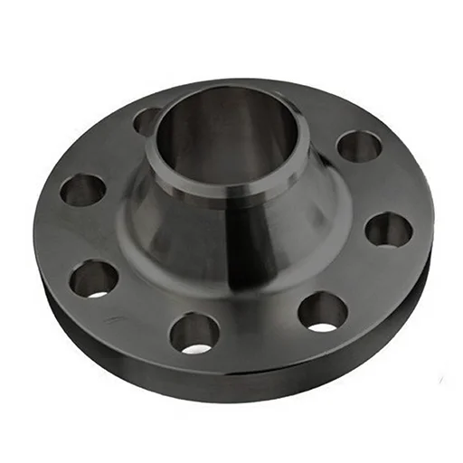
ASTM A105 Weld neck flange
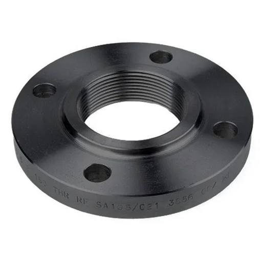
ASTM A105 Threaded Flanges
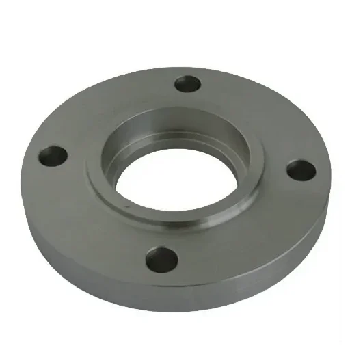
ASTM A105 Socket Weld Flanges
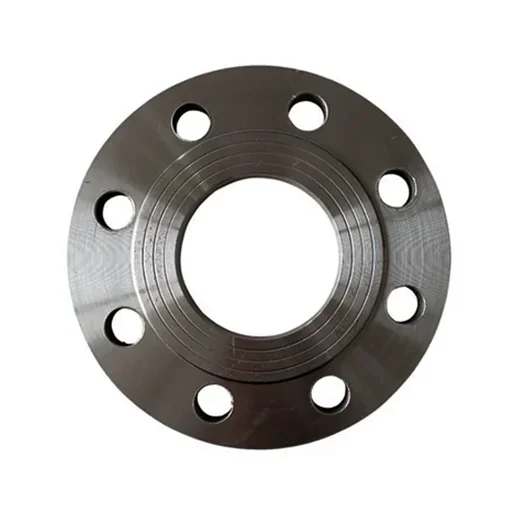
ASTM A105 Slip on Flanges
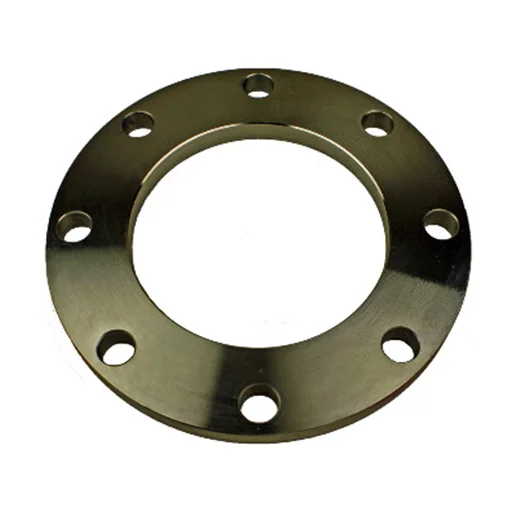
ASTM A105 Plate Flanges
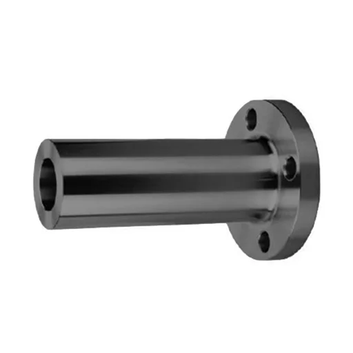
ASTM A105 Long Weld Neck Flanges
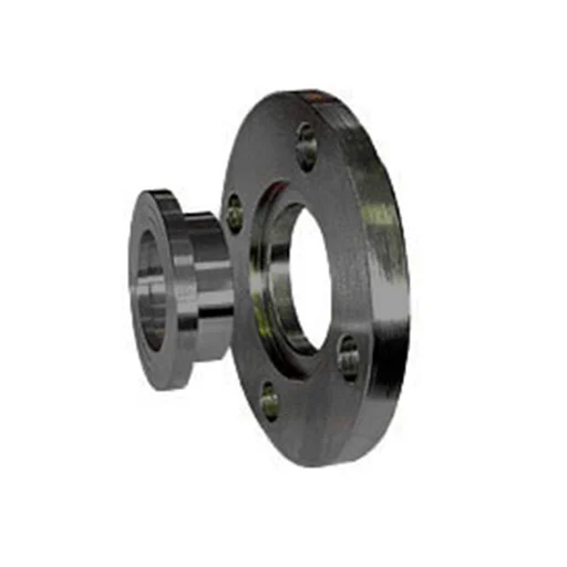
ASTM A105 Lap Joint Flanges
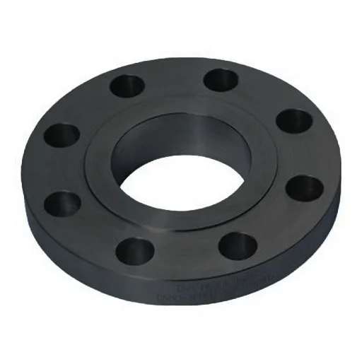
ASTM A105 Forged Flange
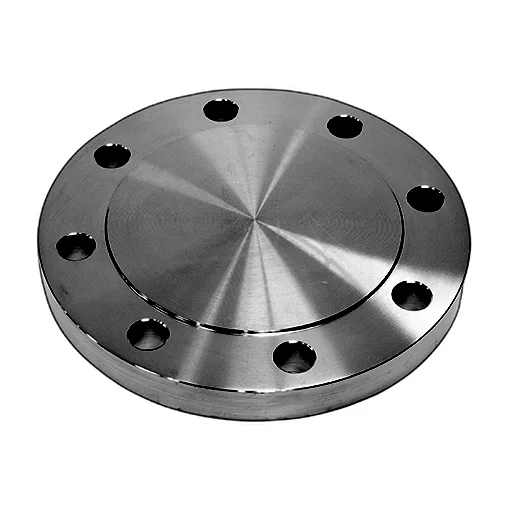
ASTM A105 Blind Flange
ASTM A105 Flanges are forged carbon steel piping components used to connect pipes, valves, pumps, and other equipment in pressure systems.
ASME B16.5 is commonly used for flange dimensions up to NPS 24, while ASME B16.47 covers larger-diameter flanges.
ASTM A105 Flanges are commonly available in Class 150, 300, 400, 600, 900, 1500, and 2500, depending on the applicable standard and size.
Yes, ASTM A105 Flanges are suitable for ambient and elevated-temperature pressure service when the applicable pressure-temperature ratings are met.
Yes, ASTM A105 Flanges can be welded using qualified welding procedures appropriate for the material, thickness, and service conditions.